Forum Replies Created
-
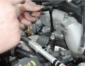
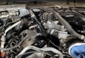
Step 7:
1. Remove the four nuts and two bolts that secure the cast air inlet section. Using a reversetorx socket to remove two bolts makes it easier to remove the air intake from the truck. (Note:Two bolts are located behind the main part of the cast air intake.)
2. Remove the PCV pipe from the driver’s and passenger’s valve covers as well as the plasticturbine interface.
3. Release the hose clamp that secures the interface to the turbine and remove the plasticturbine interface.

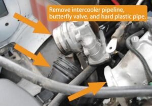
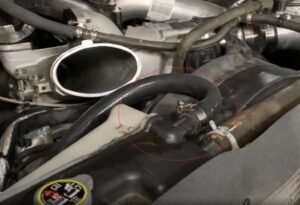
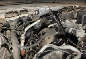
Step 6:
1. Remove the forward most piece of the cast intercooler piping, butterly valve and hardplastic tu bing.(Note: Cover the exible boot with bag to keep debris and coolant out of the intercooler.
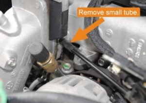
2. Remove the small tube that is attached to the cast intake next to the intake heater grid
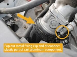
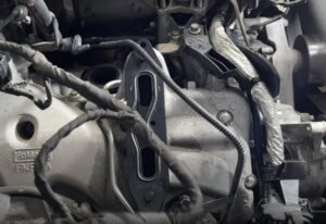
Step 5:
1. Disconnect the wire connectors at the front of the intake heater grille, remove the bolts thatsecure the connector wires to the intake side, and remove the plastic clips that secure somewires in place.
2. Pop out the metal fixing clip on the plastic intercooler pipeline and disconnect the plasticpart from the cast aluminum part.3. Remove the wire connectors and four bolts that secure the front to middle section of thecasting intercooler pipeline. At the bottom of the front section, there is a fifth bolt that secures itto the support frame. (Circled in Step5).

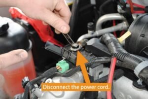
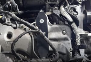
Step 4:
1. Open the plastic casing on top of the intake heater grille and disconnect the power cord.
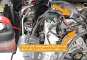
2. Remove the two bolts and one nut that secure the plastic cable tray in place.

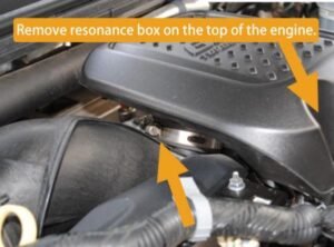
Step 3:
Remove the resonance box at the top of the engine by loosening the hose clamp at the bottomof the resonance box and removing the long bolt at the front of the resonance box.
ER-0088 2011-2019 Ford Powerstroke EGR Delete kit pdf-
This reply was modified 2 weeks, 6 days ago by
luffy@malongfei.com.
Step 17:
1.Re-install all of the intake components.2.Refill the coolant following factory specifications. Run the engine and check for leaks. Afterthe engine has reached operating temperature check coolant level and top of as needed.
Step 16:
Install the supplied coolant line from the degastank (radiator overflow tank) to the disconnectedport near the bottom passenger side of theradiator.
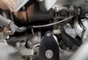
Step 15:
Remove the rear-left (passenger side closest to the firewall) bolt on the black intake “Y”.Usingfactory bolt, loosely install supplied Pressure Sensor Bracket. Using supplied small bolt,washers, and nut, bolt previously installed bracket to the pressure line hook-bracket. Tighten alhardware.
Step 14:
1. Use a clamp to insert the port of the other coolant pipeline into the adapter of the coolantpipe with a plug and clamp it tightly.2. Reconnect the PCM plug and clamp the clip tightly.

Step 13:
Reconnect the cooling liquid pipeline provided in the kit to the port where the inventory pipelinewas unplugged, ensuring that the clamp is securely fastened. lf it is inconvenient to operate.the passenger side mudguard can be removed for installation.

Step 12:
Disconnect the clamp that secures the coolant pipeline to the firewall and remove the pipelinefrom the coolant port.


Step 11:
1. Install the coolant baffle using hex head bolts and stock washers.
2. And screw the previously removed temperature sensor probe into the blocking plate.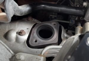
Step 10:
Use the two hexagonal bolts provided in the kit to secure the intake block O-ring.


Step 9:
Install the provided baffle, install the non fully enclosed baffe below the enclosed baffe, anduse the provided bolts to fit the flat other side with another baffle for installation
-
This reply was modified 2 weeks, 6 days ago by
-
AuthorPosts