-
-
March 28, 2025 at 2:08 am #212
Package lncludes:
- 1 *“U”Shaped Black Coolant Tube
- 1 * Exhaust Block Off Plate
- 2 * Hose Clamps
- 1*0-ring
- 1 * High Flow Intake Elbow
- 1 * M8x20 Hex Head Bolts
- 2* M8 x 25 Cap Head Bolts
- 3 *M10 x 20 Hex Head Bolts
- 2 * M8x20 Cap Head Bolts
- 1 * M8 Flange Nuts

!Before installation, confirm that:
This high -performance component does not comply with the laws and regulations for highwaydriving and cannot be used on any vehicle that has been registered or certified for use onhighways. This means that the component may only be suitable for racing cars or other off-roadvehicles. lf it is installed on vehicles driving on the highway, legal issues will be borne byoneself.
-
March 28, 2025 at 2:08 am #213
Step 1:
1. Disconnect batteries,
2. Remove the passenger side inner wheel cover to drain the engine coolant, and disconnectthe lower radiator pipe by removing the metal clip.(Note: lt is not necessary to completely pull out the pipe, just allow the coolant to flow out.)3. Loosen the hose clamps on the intake, and disconnect the MAF sensor connector.


-
March 28, 2025 at 2:08 am #214
Step 2:
1. Remove the intake pipe from the filter to the plastic turbine interface.
2. Gently pry out three rubber washers and remove the bellows and filter.


-
April 4, 2025 at 1:21 am #326
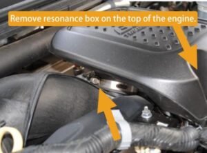
Step 3:
Remove the resonance box at the top of the engine by loosening the hose clamp at the bottomof the resonance box and removing the long bolt at the front of the resonance box.
-
April 4, 2025 at 1:24 am #331
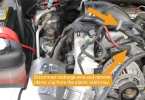
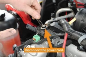
Step 4:
1. Open the plastic casing on top of the intake heater grille and disconnect the power cord.
2. Remove the two bolts and one nut that secure the plastic cable tray in place.

-
April 4, 2025 at 1:47 am #337
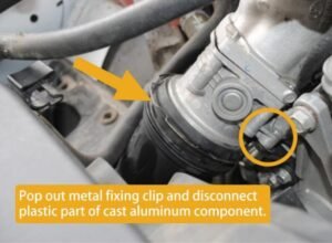
Step 5:
1. Disconnect the wire connectors at the front of the intake heater grille, remove the bolts thatsecure the connector wires to the intake side, and remove the plastic clips that secure somewires in place.
2. Pop out the metal fixing clip on the plastic intercooler pipeline and disconnect the plasticpart from the cast aluminum part.3. Remove the wire connectors and four bolts that secure the front to middle section of thecasting intercooler pipeline. At the bottom of the front section, there is a fifth bolt that secures itto the support frame. (Circled in Step5).

-
April 14, 2025 at 8:14 am #371
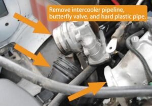
Step 6:
1. Remove the forward most piece of the cast intercooler piping, butterly valve and hardplastic tu bing.(Note: Cover the exible boot with bag to keep debris and coolant out of the intercooler.
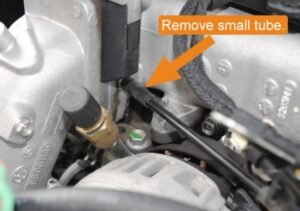
2. Remove the small tube that is attached to the cast intake next to the intake heater grid
-
April 14, 2025 at 8:22 am #374
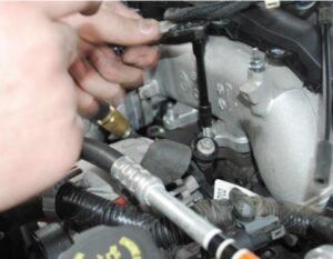
Step 7:
1. Remove the four nuts and two bolts that secure the cast air inlet section. Using a reversetorx socket to remove two bolts makes it easier to remove the air intake from the truck. (Note:Two bolts are located behind the main part of the cast air intake.)
2. Remove the PCV pipe from the driver’s and passenger’s valve covers as well as the plasticturbine interface.
3. Release the hose clamp that secures the interface to the turbine and remove the plasticturbine interface.

-
April 14, 2025 at 8:26 am #378
Step 8:
1. Remove two temperature sensors from the EGR cooler on the passenger side.Note: Someapplications do not have sensors.
2. Remove the EGR cooler fixed by six bolts. Four are located at the rear of the cooler (twobolts facing forward and two downward), and two rear bolts are located at the front of thecooler.
3. After removing the cooler, disconnect the temperature sensor at the electrical connector andremove it from the vehicle.


-
April 14, 2025 at 8:31 am #381
Step 9:
1. Remove the EGR valve fixed with two boltsKeep one of the bolts as it will be used forlater installation
2. Remove the coolant pipeline that previouslyextended from the EGR cooler to the returnwall

-
April 14, 2025 at 8:35 am #383
Step 10:
1. install the new exhaust blockO-plate using the factory gasketand provided bolts. Two M8 x 20hexagon head bolts will be screwedin from the back, and two M10 x 20hexagon head bolts will secure thebracket in place.
2. Use the provided hose clamp toinstall the “u” – shaped coolant pipe from one port on the heat exchanger back to the other porton the heat exchanger. Both ports used to have coolant lines leading to the EGR cooler.

-
April 14, 2025 at 8:46 am #386
Step 11:
1. Remove the plastic cover from the wiring harness and plug the wiring harness under thenew inflation tube.
2. Install a new intake pipe. Slide the tube into the rubber tube and tighten the bent end withbolts.


-
April 14, 2025 at 8:50 am #389
Step 12:
Use the M10 bolts provided in thekit to secure the two brackets to themotor.
Note: M8 angled nuts and bolts securethe inflation tube to the black bracketsupporting the grease valve.

-
April 14, 2025 at 8:55 am #392
Step 13:
Transfer the pressure sensor from the raw material filling tube to the new filing tube. Theinstallation bracket needs to be rotated 1800 on the sensor in order to be installed onto the newinflation tube.


-
April 14, 2025 at 8:57 am #394
Step 14:
1. Reconnect the recharge wire to the top of the AC generator.
2. install the plastic interface together with the PCV pipe onto the turbine inlet. Then install theintake resonance box on the top of the plastic turbine interface and secure it with the bottomhose clamp and the long bolt at the front ofthe resonance box.
3. Re-install the air intake and plug in the mass air ow sensor.
4. Start the engine and let it run for a few minutes. Check for leaks and add coolant ifnecessary.


-
April 14, 2025 at 8:59 am #396
-
-
AuthorPosts
- You must be logged in to reply to this topic.